Building a Simple Analog Audio Amplifier
Designing and building a simple analog audio amplifier is one of the best entry-level projects in electronics. The goal is to take a weak signal, such as from a microphone, a guitar pickup, or a mobile phone, and increase its amplitude so that it can drive a small loudspeaker.
In this article, we explore two classic approaches: a transistor-based amplifier and a circuit based on the integrated LM386. Both highlight fundamental concepts of analog electronics.
Core Concepts of Audio Amplification
- Amplification – Achieved through an active device (transistor or integrated circuit) that controls a larger current using a smaller one.
- Biasing – Resistors are used to set the correct operating point (Q-point) for the transistor or op-amp.
- AC Coupling – Capacitors block DC and allow the AC audio signal to pass, preventing distortion and protecting connected devices.
- Power Supply – Can range from 5 V (USB or batteries) to 12 V depending on the circuit design and required output power.
For more background, see Amplifier (electronics) on Wikipedia.
Example 1 – Basic Transistor Audio Amplifier
A single NPN transistor (such as BC547 or 2N3904) can be used to create a minimal amplifier.
Required Components:
- 1 × NPN transistor (BC547)
- 1 × Resistor 1 kΩ
- 1 × Resistor 10 kΩ
- 1 × Resistor 100 Ω
- 1 × Capacitor 10 µF
- 1 × Capacitor 100 µF
- 1 × Loudspeaker 8 Ω, 0.5 W
- 1 × 9 V battery or DC supply
Circuit Schematic:
      Input (signal)
           │
         [C] 10µF
           │
          R1 10k
           │
           ├───── B  BC547
           │        C
           └────────┤
                 E───┐
                     │
                   R2 100Ω
                     │
                    GND

Saída: coletor → [C] 100µF → Loudspeaker → GND
Alimentação: Vcc 9V → coletor via R3 1kΩ
- The 10 µF capacitor couples the input signal.
- R1 provides base biasing.
- R3 supplies current to the collector.
- The 100 µF capacitor couples the amplified signal to the loudspeaker.
- R2 stabilizes the emitter.
This circuit delivers milliwatt-level output, ideal for educational purposes.
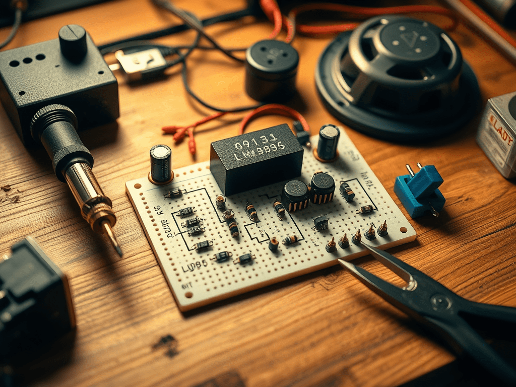
Example 2 – Audio Amplifier with LM386
For more practical applications, the LM386 integrated circuit is a classic choice. It is designed specifically for audio amplification and can output up to 1 W with minimal external components.
Basic Connections:
- Pin 3: Signal input (through 0.047 µF capacitor).
- Pin 2: Ground.
- Pin 6: Vcc (5–12 V).
- Pin 4: Ground.
- Pin 5: Output (through 220 µF capacitor to loudspeaker).
- Pin 7: Optional bypass capacitor (10 µF to ground).
The LM386 is stable, inexpensive, and widely available, making it the standard option for hobbyists building portable speakers or DIY guitar amplifiers.
For details on this chip, see LM386 on Wikipedia.
Practical Tips for Building
- Always start testing on a breadboard before soldering components.
- Keep input levels moderate to avoid distortion or damage to the transistor/IC.
- Use electrolytic capacitors with correct polarity when coupling signals.
- Ensure your power supply provides enough current for the loudspeaker.
Summary Table
| Method | Active Device | Output Power | Complexity | Typical Use Case |
|---|---|---|---|---|
| Transistor Amp | Single NPN (BC547) | Few mW | Very simple | Educational purposes |
| LM386 Amp | LM386 IC | Up to 1 W | Low | Small speakers, DIY kits |
| Op-Amp Stage | IC (e.g., 741) | Few mW – 100s mW | Medium | Pre-amps, headphones |
